



400 Hz GPU Voltage: Where Should It Be Measured?
Where Should You Measure Voltage on a 400 Hz Aircraft GPU?
A GPU display can show the expected output while a measurement at the aircraft end tells a different story. The two readings describe different points in the same electrical path. Before comparing them, an MRO team needs to identify where each voltage was measured, the load present at the time and the cable arrangement between the source and the aircraft.
The public scope of SAE ARP5015B describes 115/200 V, three-phase, 400 Hz ground power measured at the aircraft receptacle. That does not replace the aircraft documentation, airport procedure or contract acceptance criteria for a particular installation. It does make the measurement point an explicit part of the discussion.

Source-side and aircraft-side readings answer different questions
A reading at the GPU output terminals helps check what the power unit is delivering at its own connection. A reading at the aircraft receptacle includes the effect of the output cable and its connections under the stated load. Recording only one point makes it difficult to locate the cause of a difference.
For each test, note whether the aircraft load was connected, the approximate load level, the cable length and cross-section, the connector used and the instrument location. Record the phase-to-neutral or phase-to-phase quantity being measured. Without these details, two apparently conflicting voltage readings may not be comparable.
Cable planning belongs in the equipment enquiry
The cable is part of the delivery path. Its length, conductor size and condition affect the voltage available at the far end when current flows. An unloaded reading is therefore not enough to describe performance during the intended ground operation.
If a GPU serves several stands, document the longest practical route as well as the normal route. A bridge-mounted unit, fixed cabinet and mobile GPU can have different cable-handling arrangements. Do not assume that one cable set or one output setting will suit every position.
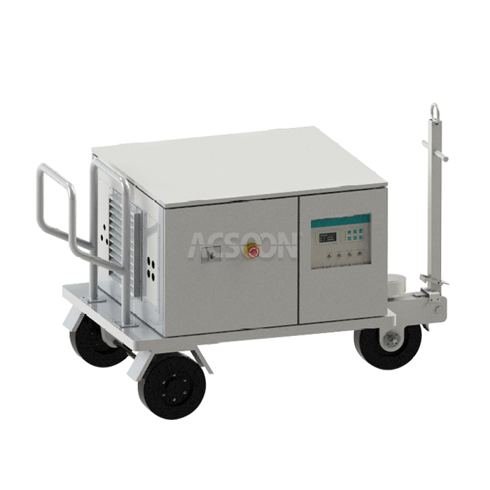
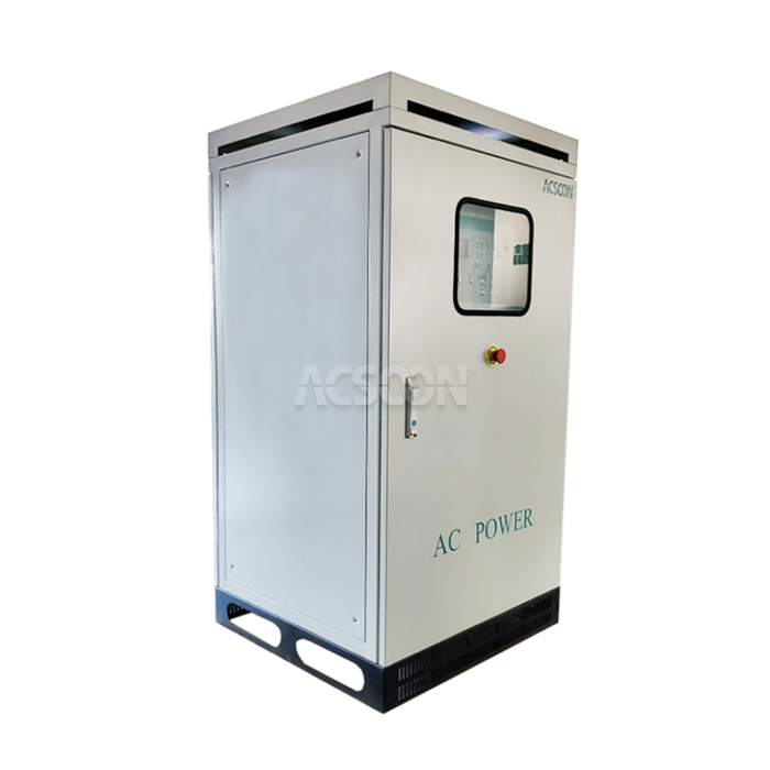
The JERRYSTAR 115 V 400 Hz aircraft GPU product page is a product reference. For another configuration view, see the ACSOON GPU400 page. These pages do not establish a project-specific aircraft-side voltage tolerance. Any compensation setting or accessory should be confirmed for the selected model and cable configuration.
A short acceptance record
An RFQ or test sheet can state five things: the applicable requirement, the aircraft-side measurement point, the load condition, the cable and connector configuration, and the instrument or method used. Record the source-side reading as a diagnostic value as well. If the project requires a tolerance, take it from the approved aircraft or project specification rather than a generic marketing figure.
For a technical review, send the aircraft interface requirement, expected load, proposed cable route and acceptance method. That information allows the GPU and cable configuration to be discussed together.